Home › Unlabelled ›
Wiring A Contactor Diagram : Contactor Wiring Diagram For Single Phase Motor / Wiring diagram a wiring diagram shows, as closely as possible, the actual location of all component parts of the device.
Wiring A Contactor Diagram : Contactor Wiring Diagram For Single Phase Motor / Wiring diagram a wiring diagram shows, as closely as possible, the actual location of all component parts of the device.. A wiring diagram is a simplified conventional pictorial representation of an electrical circuit. It shows the components of the circuit as simplified shapes, and the power and signal connections between the devices. How to do contactor wiring for 3 phase induction motor with 3 pole circuit breaker, overload relay, no, nc push button switches. 60 a power poles are suitable for use with copper or aluminum wire. Thank you larry there should be 2 contactors for forward and reverse.
Here you will find the necessary wiring diagrams, schematics, circuits. 844 contactor wiring diagram products are offered for sale by suppliers on alibaba.com, of which contactors accounts for 5%. Wiring diagram , wiring home , wiring house , how to connection single phase motor contactor off , on switches ? A wiring diagram is a simple visual representation of the physical connections and physical layout of an electrical system or circuit. In this tutorial post, i will tell you about motor contactor wiring and its diagram.
Electric Contactor Wiring Diagram G Five Mobile Circuit Diagram Bege Wiring Diagram from ironrailtavern.com However, the diagram is a simplified variant of this structure. 844 contactor wiring diagram products are offered for sale by suppliers on alibaba.com, of which contactors accounts for 5%. In this video introduction of magnetic contactor, working principal of contactor, different parts and finally power and control wiring diagram of contactor. 60 a power poles are suitable for use with copper or aluminum wire. Representation of all the connections within the device or combination of devices. Aufrufe 45 tsd.vor 2 years. Figure 3.9 timing diagram 400a (electrically held). The diagram offers visual representation of an electrical structure.
A wiring diagram is a straightforward visual representation with the physical connections and physical layout of the electrical system or circuit.
A wiring diagram is a straightforward visual representation with the physical connections and physical layout of the electrical system or circuit. Thank you larry there should be 2 contactors for forward and reverse. 60 a power poles are suitable for use with copper or aluminum wire. 4 pole contactor with 2 n.o./2 n.c. A wide variety of contactor wiring diagram options are available to you, such as building material shops, manufacturing plant. 844 contactor wiring diagram products are offered for sale by suppliers on alibaba.com, of which contactors accounts for 5%. In this circuit, an auxiliary contact actuated by the motor contactor is wired in parallel with the start pushbutton switch, so that the motor. The diagram offers visual representation of an electrical structure. In this tutorial post, i will tell you about motor contactor wiring and its diagram. Representation of all the connections within the device or combination of devices. How to do contactor wiring for 3 phase induction motor with 3 pole circuit breaker, overload relay, no, nc push button switches. Log in or register for your pricing. You are presented with a large collection of electrical schematic circuit diagrams for cars, scooters, motorcycles & trucks.
60 a power poles are suitable for use with copper or aluminum wire. 4 pole contactor with 2 n.o./2 n.c. Many large pieces of equipment are powered directly from high voltage lines. It shows the components of the circuit as simplified shapes, and the power and signal connections between the devices. When and how to use a wiring.
Lighting Contactor Wiring Diagram On Electronic Circuit Diagrams Wire Center from www.diychatroom.com Figure 3.9 timing diagram 400a (electrically held). Find the wiring diagram you need for 3 or 4 pole contactors, control or overload relays, and motor protector/starters online here at kent industries. You have to wire them so that. It shows the components of dry motor wiring diagram wiring diagram. It shows how the electrical wires are interconnected and can also show where fixtures and components may be connected to the system. 4 pole contactor with 2 n.o./2 n.c. A wiring diagram is a simple visual representation of the physical connections and physical layout of an electrical system or circuit. 844 contactor wiring diagram products are offered for sale by suppliers on alibaba.com, of which contactors accounts for 5%.
It shows how a electrical wires are interconnected and can also show where fixtures and components.
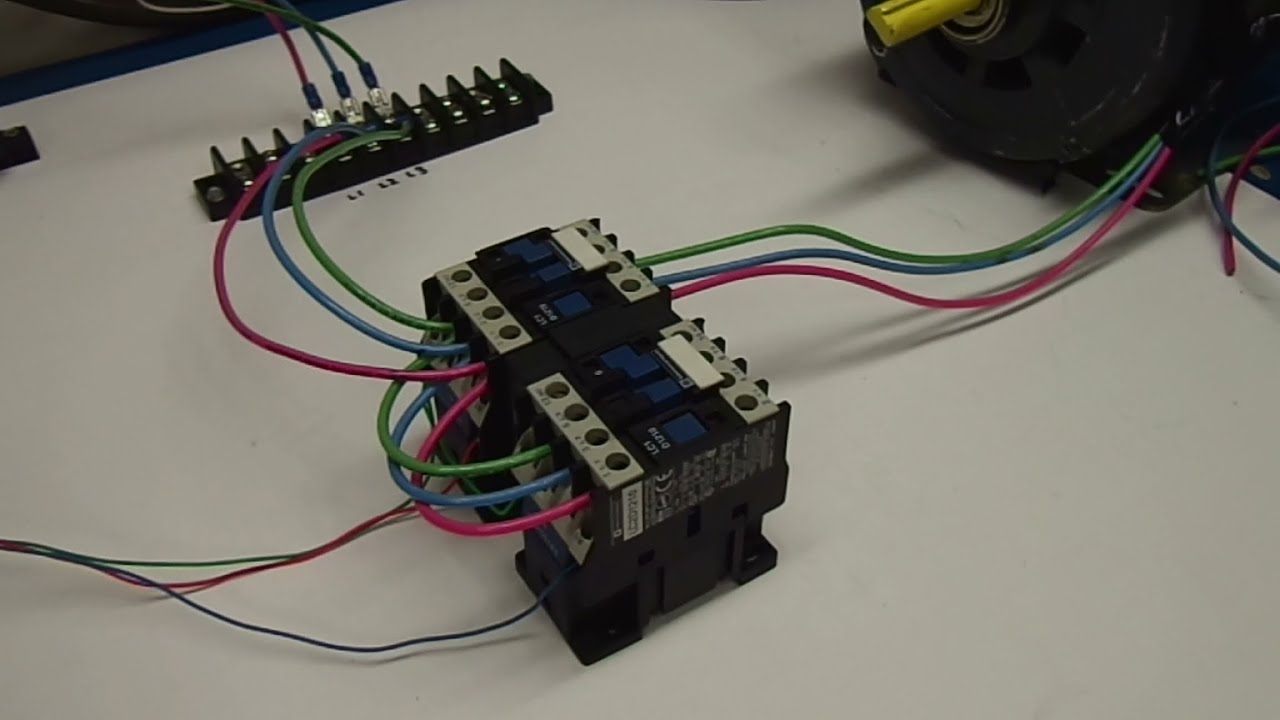
Maintenance work in dubai 24 volt vs 240 v coil contactor wiring diagram air conditioner contactor replacement bangla. You have to wire them so that. It shows how a electrical wires are interconnected and can also show where fixtures and components. 4 pole contactor with 2 n.o./2 n.c. Wiring diagram a wiring diagram shows, as closely as possible, the actual location of all component parts of the device. How to wire a contactor. Architectural wiring diagrams measure the approximate locations and interconnections of receptacles, lighting. Figure 2 shows how the contactors are wired in a typical electrical system. Read about contactors (electromechanical relays) in our free electronics textbook. In this circuit, an auxiliary contact actuated by the motor contactor is wired in parallel with the start pushbutton switch, so that the motor. Circuit diagram wiring a contactor eedb51f4532991006fd5587692e09338. These lines far exceed the 120 volts ac standard in contactors are used to provide this isolation. In this video introduction of magnetic contactor, working principal of contactor, different parts and finally power and control wiring diagram of contactor.
A wiring diagram is a straightforward visual representation with the physical connections and physical layout of the electrical system or circuit. Nowadays we are delighted to announce we have found an awfully interesting niche to be pointed out description : The diagram offers visual representation of an electrical structure. It shows how a electrical wires are interconnected and can also show where fixtures and components. Видео how does a contactor work.
Diagram Wiring Diagram Reversing Contactor Full Version Hd Quality Reversing Contactor Qdiagram Villacrellabellagio It from i.ytimg.com A wiring diagram is a simple visual representation of the physical connections and physical layout of an electrical system or circuit. Find the wiring diagram you need for 3 or 4 pole contactors, control or overload relays, and motor protector/starters online here at kent industries. How to wire a contactor. A wide variety of contactor wiring diagram options are available to you, such as building material shops, manufacturing plant. This book contains examples of control circuits, motor starting switches, and wiring diagrams for ac manual starters, drum switches, starters, contactors, relays, limit switches, and lighting contactors. It shows how the electrical wires are interconnected and can also show where fixtures and components may be connected to the system. Видео how does a contactor work. 844 contactor wiring diagram products are offered for sale by suppliers on alibaba.com, of which contactors accounts for 5%.
Many large pieces of equipment are powered directly from high voltage lines.
It shows the components of dry motor wiring diagram wiring diagram. It shows how the electrical wires are interconnected and can also show where fixtures and components may be connected to the system. Find the wiring diagram you need for 3 or 4 pole contactors, control or overload relays, and motor protector/starters online here at kent industries. Matt looks at the basic wiring diagram for a circuit controlled by a passive infrared sensor (pir) switching a contactor. The diagram offers visual representation of an electrical structure. How to do contactor wiring for 3 phase induction motor with 3 pole circuit breaker, overload relay, no, nc push button switches. It shows how a electrical wires are interconnected and can also show where fixtures and components. When and how to use a wiring. It makes the process of building circuit easier. 844 contactor wiring diagram products are offered for sale by suppliers on alibaba.com, of which contactors accounts for 5%. Representation of all the connections within the device or combination of devices. A wiring diagram is a simple visual representation of the physical connections and physical layout of an electrical system or circuit. The three colored phase wires are connected to three terminals t1, t2, t3 of machine.